ASTS
Telemetry system for transmitting measured status variables during the winch launch
Purpose
- Support for the winch operator
- Improvement of winch operator training
- Control of the winch tow
- Improving safety
- Acquisition of meteorological data
- Investigation of the winch launch
- Validation of theoretical models
Measured Variables (Glider)
- Air speed
- Altitude
- GPS position
- Acceleration in longitudinal and vertical direction
- Rudder angle
Measured Variables (Winch)
- Rope speed
- Rope force
Research
- Influence of towing speed, flap position and center of gravity on the towing height
- Energy balance of the winch tow
Meteorology
- Wind profile over altitude
- Temperature profile over altitude and time
Additional Use
- Mapping of thermals in the immediate vicinity of the airfield
- Visualization of the aerodrome traffic
Theoretical Principles
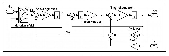
- AK-7 (Modeling of the winch launch)
- Design of a fuzzy controller for winch launch (C. Wurm)
Radio Transmission
- Frequency range: 869 MHz (ISM band)
- Transmission power: 500 mW
- Antennas: Lambda/4 antennas
- Range: >2km
Details
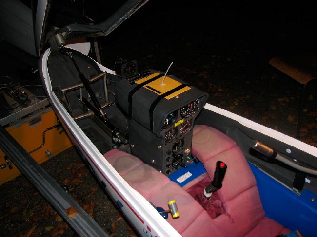
The antenna, mounted for flight tests in the glider AK-5b (Akaflieg Karlsruhe, 1996). The transmitter unit and the pressure measuring equipment are located in the instrument panel. At the bottom right of the I-pillar there is a plug for connecting a display for calibrating the airspeed measurement and two buttons for operation. The antenna can later be fitted under the instrument panel cover or on the landing gear.
The receiver board, mounted in the AFK-3 winch (Akaflieg Karlsruhe, 1987). A similar unit is located in the aircraft as a transmitter. The receiver unit coordinates the radio traffic for several airplanes and controls the display units (see below).
The receiving antenna (cable on the right) is mounted on the roof of the winch.
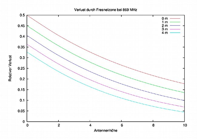
Not only the direct propagation path of the radio waves is relevant for undisturbed transmission. Obstacles in an ellipsoidal area around the line of sight (Fresnel zone) also lead to losses.
The adjacent graph shows the relative loss of transmission power caused by the ground, depending on the height of the two antennas.
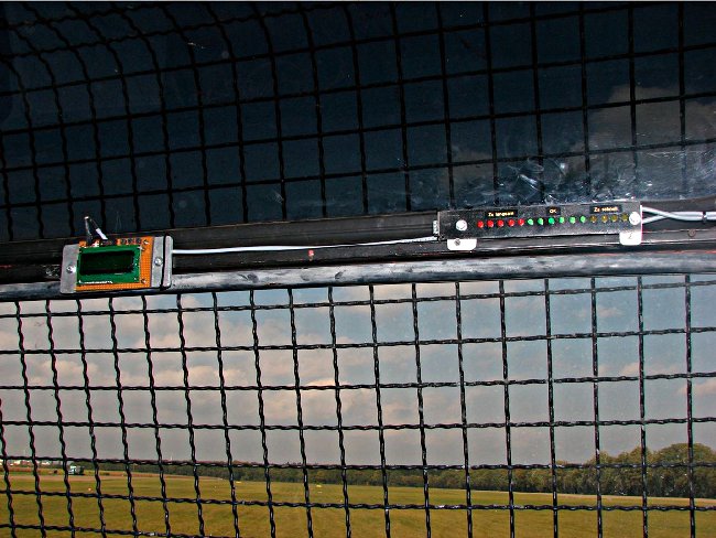
The LED line on the right-hand side is located in the winch operator’s field of vision and displays the deviation of the towing speed from the target speed. The alphanumeric display on the left provides further information, such as the detected aircraft type and the current altitude. The target speed can also be changed manually and other settings can be made here.
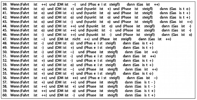
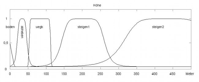
This is a fuzzy controller, i.e. a knowledge-based system. The designations are derived from the measured variables using a membership function (see below). Several rules can apply simultaneously.