AK-1
Performance Glider with Retractable Motor
As early as 1955, the Akaflieg Karlsruhe began work on the development of motor gliders with good gliding performance, as the ability to self-launch was seen as a significant advantage in addition to the increase in operating radius: fewer ground personnel to carry out flight operations, lower outlanding risk, easy transportation. In addition, the idea of “flight touring”, as envisioned by Wolf Hirth, one of the greatest advocates of the motor glider idea, was of course also appealing during the planning phase.
Difficulty
The fundamental problem of motor glider construction lay in the difficulty of installing an engine in a glider without significantly changing the performance and flight characteristics. The reason for a deterioration, apart from the increase in overall weight, is primarily to be found in the aerodynamic area. A permanently installed power unit generates a noticeable drag when not in use.
A better solution, on the other hand, was the retractable drive unit, the realization of which, however, posed enormous difficulties in terms of design. The procurement of a suitable engine alone was a major problem that caused many a motor glider project to fail or led to motor glider projects being converted into pure gliders after a short time.
Initial Drafts
In the 1950s, the first designs were created, e.g. a motor glider with pressure propellers on the trailing edge of the wing between the double tail unit beams. Although the calculations were quite advanced, the construction of this ambitious project could not be considered due to a lack of free working capacity (the research contracts awarded by the state of Baden-Württemberg for winch launching and winch ropes were running in parallel).
Nevertheless, the idea was too tempting to give up without further ado. For this reason, the task was changed so that the company decided not to build its own fuselage and wing and instead planned to install an engine in an existing glider. The choice fell on the Ka7 two-seater, on the front seat of which an engine was to be installed. The propeller, driven by a V-belt, was to be extended forward from the tip of the fuselage for powered flight.
Another study envisaged the installation of the engine on the rear seat of a Bergfalken II: the propeller was to be swung upwards out of the fuselage on a boom. Both designs were based on an American 4-cylinder two-stroke engine with 40 hp at 4000 rpm, which was the only engine with a sufficient power-to-weight ratio at the time.
When it was learned in 1959 that production of the newly developed engine had already been discontinued, the Akaflieg’s motor glider ideas were put on ice for the time being.
Objectives of the AK-1 Project
In 1965, the time had finally come: the research contracts for the investigation of tow ropes and winch launching as well as the self-construction of a launch winch were completed. With the Hirth F10, a usable drive was finally available, so that the design of a motor glider was begun with the following objective:
- Self-launch capability without auxiliary personnel
- Gliding performance corresponding to the standard class (e.g. Ka6)
- Minimal maintenance and overhaul costs
- Weather-resistant construction/materials
Metal / Plastic Construction
The Akaflieg wanted to break new ground in aircraft construction. For a motor glider, metal appeared to be more favorable than the still young GRP construction method, the current spread of which was by no means foreseeable at the time. Above all, the higher rigidity of the wings, the elimination of surface treatment (painting/finishing) and GRP mold construction and the well-known weather resistance of metal aircraft were seen as decisive advantages. The newly developed metal bonding technology made it possible to largely dispense with aerodynamically disruptive riveted joints.
Wings and Tail Unit
A U-shaped spar was used for the wing, which was created by gluing and riveting the web plate, upper and lower chord with reinforcing straps and fittings (2300 rivets). Seven shaping metal flanging ribs were then placed between which Conticell hard foam ribs were placed every 100 mm. This meant that the exact profile contour could be easily drawn out over the metal ribs.
Hard foam stringers between the ribs are intended to reduce the tendency of the only 0.5 mm thick aluminum sheet cladding to buckle. These were fitted after pre-bending and riveted to the spar straps and the seven metal ribs. The rear wing was manufactured in the same way.
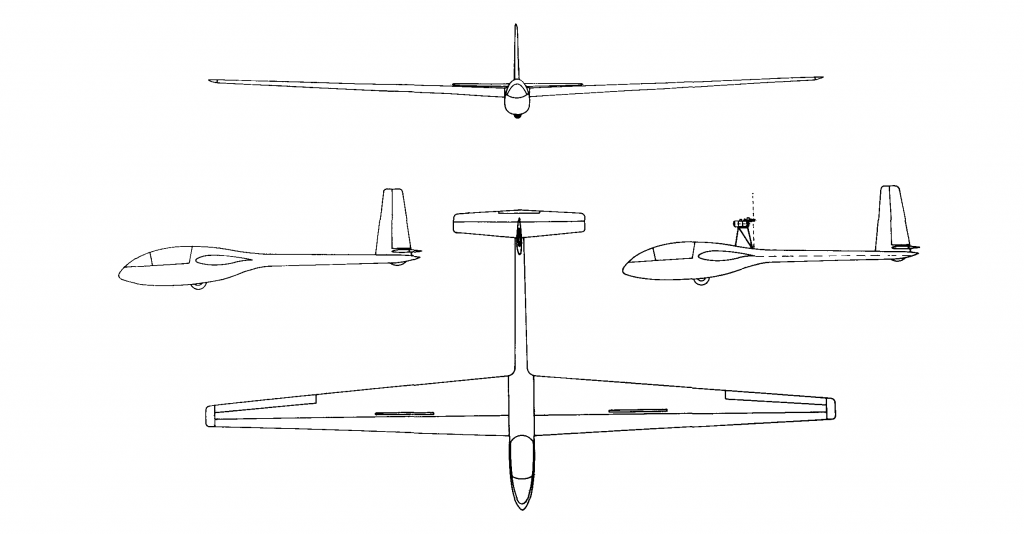
With the exception of the rudder, which is of conventional wooden construction, all the control surfaces were manufactured according to the same principle as the wings. In order to avoid vibration problems caused by the propeller jet hitting the tail unit, the AK-1 was fitted with a cruciform tail unit instead of a modern T-tail unit. Power is only transmitted to the rudder via cables, all other control elements are actuated via push rods.
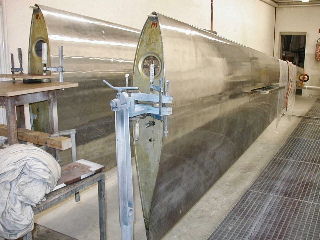
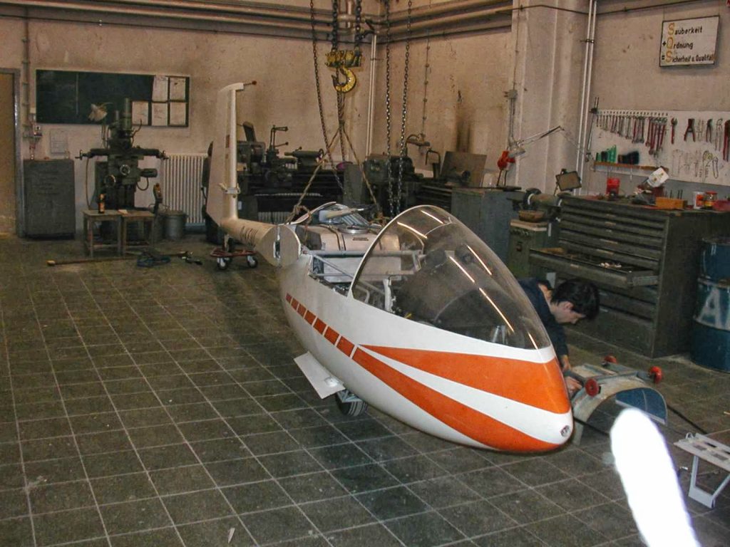
Fuselage and Motor
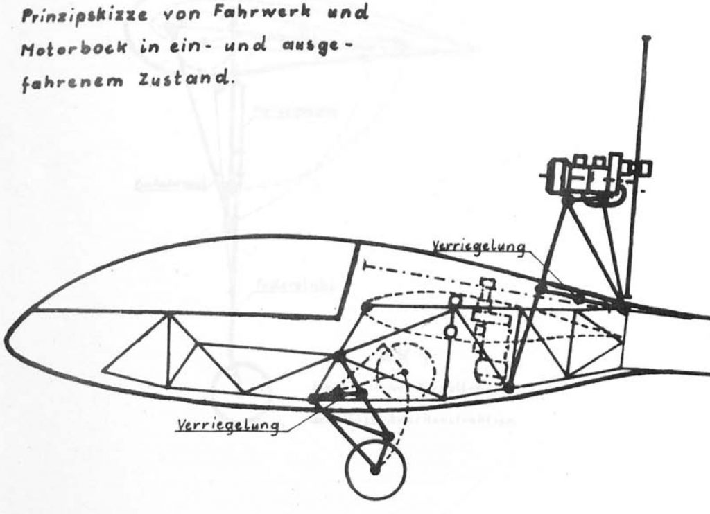
The following concept appeared to be the most favorable for the hull: a hull boat covered with a GRP shell made of a tubular steel truss, to which a conical duralumin tube without frames and stringers was to be connected as a tail unit support. Above all, the truss construction greatly simplified the installation of the landing gear, the controls and the engine with its complex kinematics for retraction and extension and considerably improved the cumbersome maintenance work due to the lack of space by making it possible to simply unscrew the GRP shell.
The four-cylinder two-stroke F10A engine from Hirth was used as the drive, which with its 28 hp drives a 1.3 m diameter propeller. The engine retraction mechanism was understandably of the greatest importance in the design of the fuselage. The chosen principle of extending the propeller together with the engine has the advantage that no cooling problems occur and difficulties with power transmission are avoided. The retraction and extension is carried out mechanically, with the pilot being assisted by twelve pre-tensioned rubber cables. The openings in the fuselage are closed by three flaps when extended and seven flaps when retracted. In addition to the engine and fuel tank, which was installed between the spar bridge and cockpit, the landing gear also had to be accommodated in the fuselage. Initially, a rather high landing gear with a 38 cm wheel and disk springs was installed in order to achieve the shortest possible take-off distance due to the high angle of attack. However, as the controllability of the aircraft at take-off speed was too poor in this configuration, the landing gear was soon reduced to its current level.
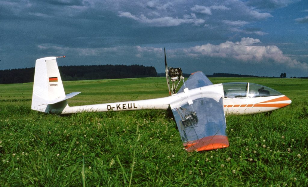
AK-1 Takeoff
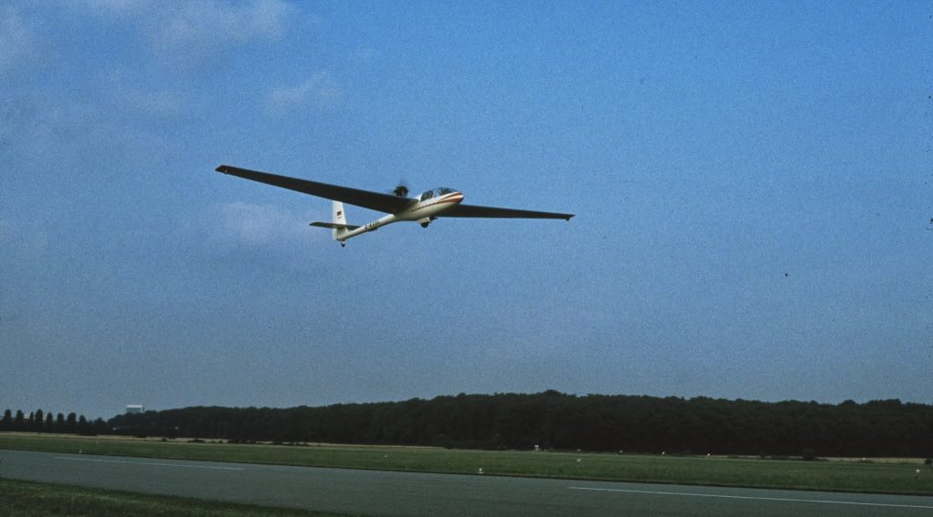
On January 9, 1971, the AK-1 rises into the air for the first time. On July 7, 1973, it was christened “Mischl” by Professor Diem to express its character as a hybrid of powered aircraft and glider.
After completion of the flight tests, it was certified by the LBA and was used by all Akaflieg pilots with a motor glider license. In terms of its performance, it meets the design targets of the 1960s and is therefore no longer competitive as a competition aircraft today. In 2011, the AK-1 was handed over to the German Museum in Schleißheim and is still on display there today. The proliferation of motor gliders with retractable engines since the 1980s is a nice confirmation of the AK-1 concept developed in the early 1960s.